Fermilab has a strong superconducting (SC) accelerator magnet R&D program, which is natural for a laboratory which operated one of the largest SC accelerators in the world, the Tevatron. The history of SC accelerator magnet development at Fermilab includes 4T NbTi magnets for the Tevatron in the 70’s-80’s, 7T NbTi dipole models for the (then planned) Superconducting Super Colider in the second part of the 80’s, and 9T NbTi High Gradient quadrupole magnets for the LHC in the second part of the 90’s.
The pursuit to extend energy and luminosity frontiers requires the development of new magnet technologies and materials. The back-bone of the current R&D activities is the Nb3Sn superconductor technology development and different types of magnet are being fabricated and tested with it. High temperature superconductor materials for accelerator magnet applications are also being investigated. The research was/is being conducted as part of Magnet Development Program and Hi-Lumi-LHC and supported by the Superconducting Strand and Cable R&D Lab.
Superconducting magnets R&D
10 T Dipoles for VLHC
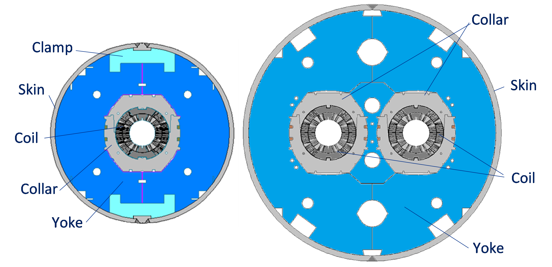
The design and main parameters of FNAL dipole models of the HFDA series are described in [1]. These magnets have been developed as baseline dipoles for the VLHC, which was extensively studied in the US in 2000s. The cross section of the dipole cold mass is shown in the figure (left). This magnet was designed to provide a nominal field of 10 to 11 T (Bmax~12 T) in a 43.5 mm aperture at an operating temperature of 4.5 K. The main R&D goal of this model magnet series was to develop a robust Nb3Sn coil technology based on the Wind&React (W&R) approach and an inexpensive mechanical structure suitable for industrialization. The magnet design was based on a two-layer shell-type coil and a cold iron yoke. To reduce the magnet cost, a compact collarless mechanical structure with Al clamps, a 400 mm iron yoke and a 10 mm stainless steel skin were used.
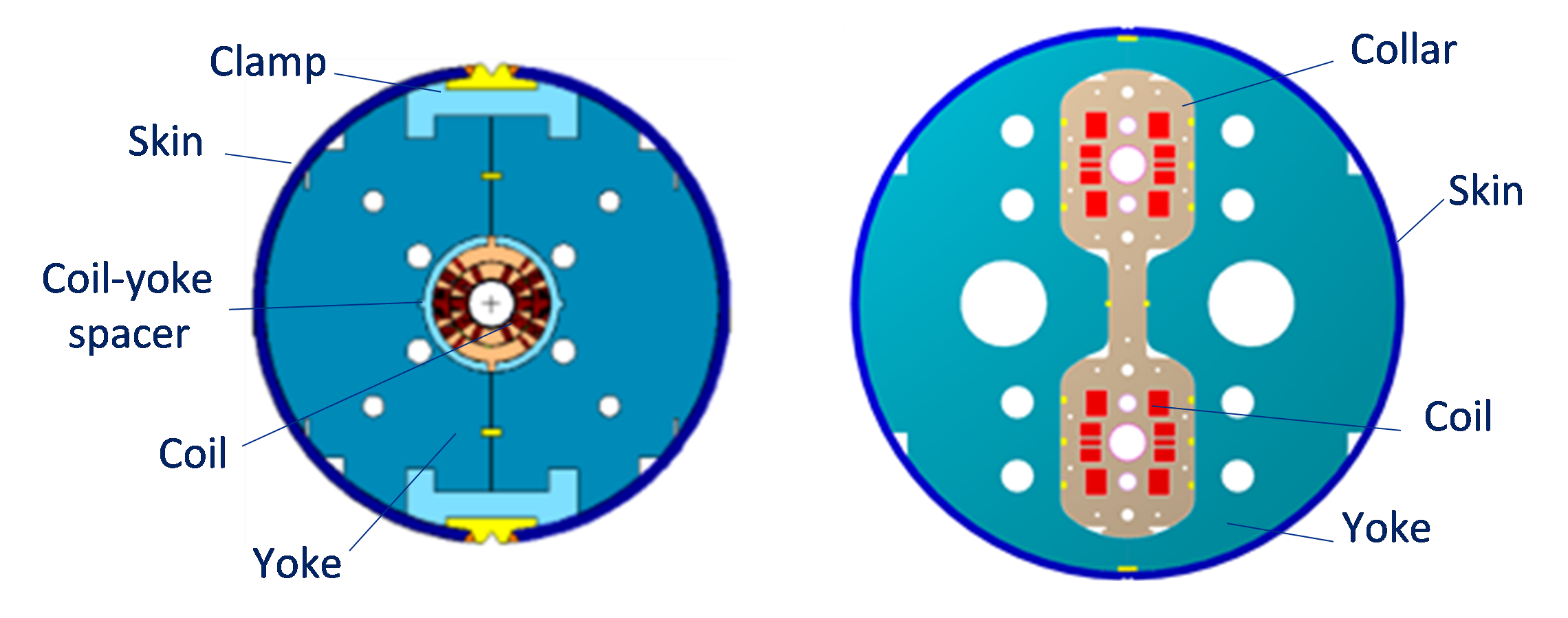
Cross section of single-aperture HFDA dipole (left) and twin-aperture common coil HFDC dipole (right).
FNAL also developed a common coil dipole design (HFDC), which meets the VLHC requirements and allows using the React&Wind (R&W) technology [1]. The main features of this magnet are a wide 60-strand cable based on high Jc 0.7 mm Nb3Sn strand, a single-layer coil confined in an innovative collar structure with two 40 mm bores and a cold, vertically-split iron yoke. The HFDC dipole cross section is shown in the figure 3 (right). The goals of this work were to study the possibilities and limitations of the R&W technology and develop a 10 T Nb3Sn accelerator quality common coil dipole based on this approach. An advantage of the R&W method is the possibility of using traditional materials developed for NbTi accelerator magnets in the past 30 years.
[1] A.V. Zlobin et al., IEEE Trans. on Appl. Supercond., v. 15, no. 2, p. 1113 (2005).
90-mm aperture Quadrupoles for LHC
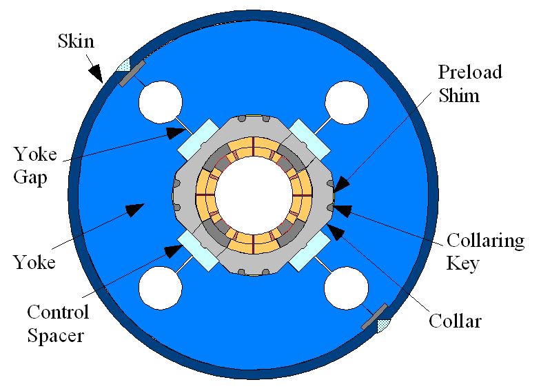
TQC quadrupole cross section.
The design and parameters of FNAL’s quadrupole models of the TQC series are described in [1]. These magnets were proposed and used as a technological model of a new generation of large-aperture IR quadrupoles for the planned LHC luminosity upgrade. The TQC cross section is shown in the figure. This model magnet series was designed to provide the same nominal field gradient of 200 T/m (Gmax~250 T/m) in a 90-mm aperture at the same operating temperature of 1.9 K as the present 70-mm NbTi LHC IR quadrupoles (MQXB). The quadrupole design consists of a two-layer shell-type coil and a cold iron yoke. The design and technology of quadrupole coils used in TQC models largely rested on the results of the HFDA dipole program described above. The TQC mechanical structure is based on a slightly modified mechanical structure of the present LHC MQXB. It includes a 25-mm thick stainless steel collar, a 400-mm iron yoke and a 12 mm thick stainless steel skin.
[1] A.V. Zlobin, “Status of Nb3Sn Accelerator Magnet R&D at Fermilab”, CERN Yellow Report CERN-2011-003, p. 50 [arXiv:1108.1869].
11 T Dipoles for LHC Collimation System Upgrade
Additional collimators are planned in the LHC Dispersion Suppression areas around points 2, 3, 7, and at the CMS and ATLAS detectors. Creating room in the ring for these collimators requires replacing a number of 8.33 T 15 m long NbTi main dipoles (MB) with shorter 11 T Nb3Sn dipoles (MBH). The latter need to be compatible with the LHC lattice and main systems and deliver the same integrated bending strength at the LHC nominal operation current.
Single-aperture MBHSP (left) and twin-aperture MBHDP (right) designs of the 11 T dipole.
Design concepts of the 11 T Nb3Sn dipole developed at FNAL in collaboration with CERN for LHC upgrades in both single-aperture and twin-aperture configurations are described in [1], [2]. The dipole design features 2-layer shell-type Nb3Sn coils, separate stainless steel collars for each aperture and a MB yoke which was modified in the area of the collar yoke interface. The magnet coil was designed to provide a dipole field of 11 T in a 60 mm aperture at the LHC nominal operation current of 11.85 kA with 20% margin along the magnet load line. The chosen coil aperture of 60 mm is slightly larger than the MB dipole aperture, which avoids bending the Nb3Sn coils to accommodate the LHC beam sagitta. The figure shows the cross sections of the 11 T dipole in both single-aperture and twin-aperture configurations.
[1] M. Karppinen et al., IEEE Trans. on Appl. Supercond., v. 22, no. 3, 4901504 (2012).
[2] A.V. Zlobin et al., Proc. of PAC2011, NYC, 2011, p. 1460.
15 T Dipoles for a Future Circular Collider
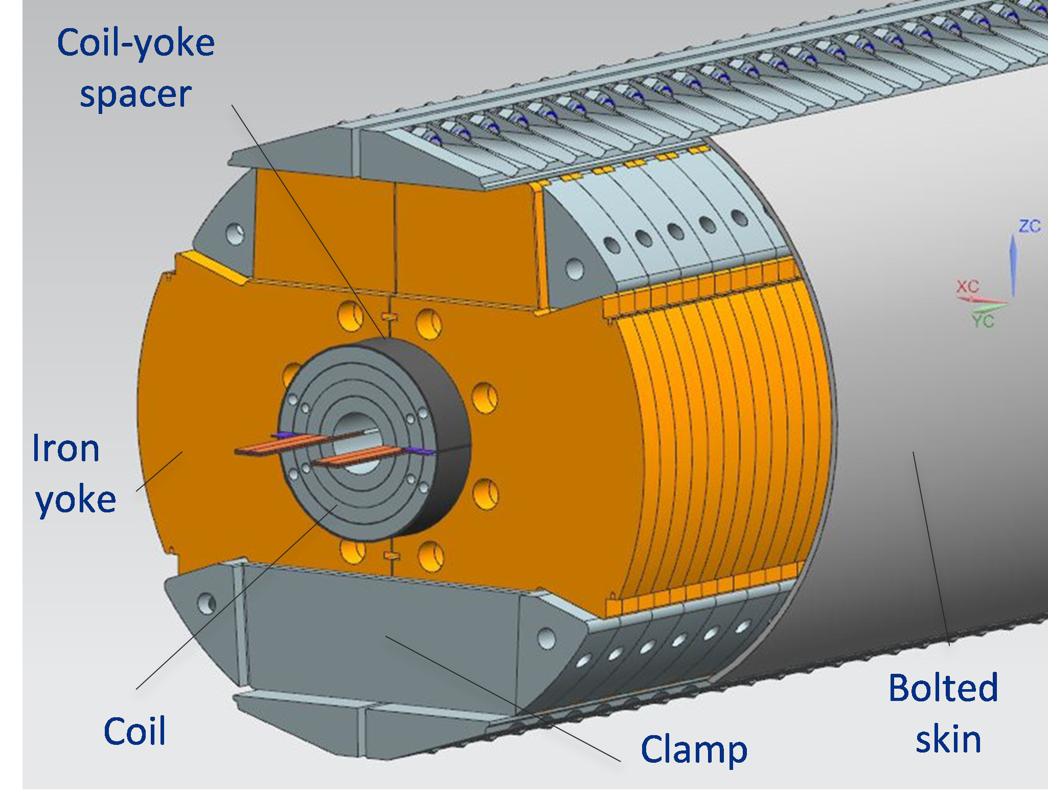
Cold mass design of the 15 T dipole demonstrator.
To build a ~100 TeV Hadron Collider (HC) in a ~100 km tunnel, ~15 T dipoles operating at 1.9 or 4.5 K with 15 to 20% margin are needed. A nominal operating field up to 15 to 16 T can be provided by the Nb3Sn technology. A practical demonstration of this field level in accelerator-quality magnets and a substantial reduction of magnet costs are key conditions for the realization of such a machine.
FNAL has started the development of a 15 T Nb3Sn dipole demonstrator for a 100 TeV scale HC based on the optimized “cos-theta” coil design [1]. The design concept of the 15 T dipole demonstrator cold mass is shown in the figure [2]. The 4-layer graded coil is supported by a vertically split iron yoke, aluminum clamps, and a thick stainless steel skin. The coil assembly, surrounded by a 2 mm stainless steel spacer, is placed in between the two half-yokes and braced with two clamps. The skin and the clamps are pre-tensioned under a press to provide an initial coil pre-stress at room temperature. The axial Lorentz forces on the coil ends are intercepted by two thick end plates connected by eight tie rods running through dedicated holes in the iron yoke.
[1] A.V. Zlobin et al., Proc. of IPAC2015, Richmond, VA, 2015, p. 3365
[2] I. Novitski et al., IEEE Trans. on Appl. Supercond., v. 26, no.2, 2016.
Summary of Magnet Performance

Maximum field reached in the FNAL dipole and quadrupole models (solid markers) and mirror configurations (open markers).
The magnet models were tested at FNAL in liquid helium at 4.5 K, 1.9 K and intermediate temperatures. The figure shows the maximum field reached in the FNAL Nb3Sn dipole and quadrupole models as well as in special coil test structures, also called “mirror configurations”, where only one coil is tested and the others are replaced by special iron blocks.
Superconducting materials R&D
Superconducting wires
Cross sections of composite Nb3Sn , Nb3Al and Bi-2212 wires are shown in the figure. Their actual potential for high field accelerator magnets is being extensively studied. The critical current density Jc of Nb3Sn more than doubled between 1998 and 2007 thanks to the US Conductor Development Program. As a result, the Jc at 12 T of Nb3Sn wires exceeds the Jc at 5 T of NbTi wires. However, a higher Jc at 15 T and lower costs are desired for Nb3Sn . A large progress was made in Japan for Nb3Al composite wire production and performance thanks to the Rapid-Heating Quenching Transformation process. Nb3Al has lower strain sensitivity than Nb3Sn and thus potential for operation at higher forces. Nevertheless, there are still significant fabrication challenges to be solved to improve Jc and make Nb3Al cost competitive with Nb3Sn . Heat treating Bi-2212 under high pressure increases the wire Jc. However, this result has to be demonstrated for multi-strand cables and coils in order to be useful for accelerator magnets.
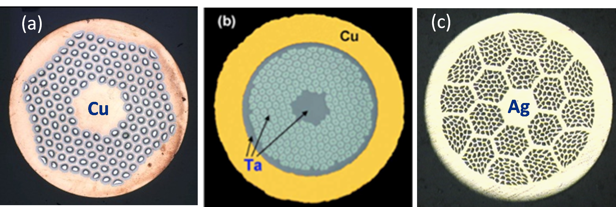
Cross sections of Nb3Sn (left), Nb3Al (center) and Bi-2212 (right) composite wires. Courtesy of OST (USA) and NIMS (Japan).
Nb3Sn composite wires are currently produced using three main methods: bronze, internal tin (IT), and powder-in-tube (PIT). At present the IT Restacked-Rod Process (RRP®) by Oxford Superconducting Technology (OST) and PIT by Bruker-EAS are the only two wires with sufficiently high Jc for HEP applications that are available in large quantities from industry. FNAL’s main contributions to high field Nb3Sn conductor advances include the development and optimization with industry of composite wires with improved stability problem due to flux jumps and low sensitivity to transverse plastic deformations. These results are widely recognized, and the wires were adopted by CERN and by the LHC Accelerator Research Program (LARP). FNAL also developed with NIMS, KEK and Japanese industry a Nb3Al wire and Rutherford cable that established the use of this conductor in magnets for the first time [1].
[1] R. Yamada et al., IEEE Trans. on Appl. Supercond., v. 17, no. 2, p. 1461 (2007).
Rutherford cable R&D
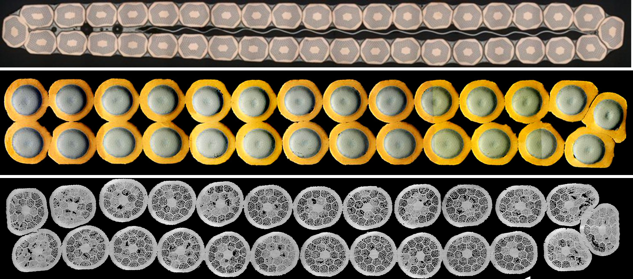
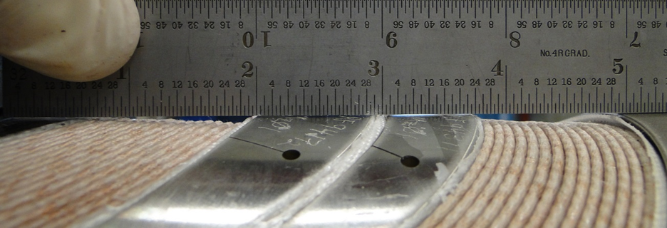
Cross sections of keystoned 40-strand (0.7 mm) Nb3Sn Rutherford cable with an 11 mm wide and 25 m thick stainless steel core (top); 27-strand (1 mm) Nb3Al rectangular cable (middle); 25-strand (0.8 mm) Bi-2212 rectangular cable (bottom).
FNAL has been performing development and optimization of Rutherford cables based on Bi-2212 wires with the goal of demonstrating this superconductor for use in high field accelerator magnets. Examples of Rutherford cable based on Nb3Sn, Nb3Al and Bi-2212 strands are shown in the figure. Cable development is performed by designing and fabricating samples of different geometries using state-of-the-art wires, with the purpose of studying the effect of cable parameters and processing on its performance. This includes for instance the sensitivity of electrical properties and internal structure to cable compaction, measurements of cable stability and AC losses, measurements of 3D cable expansion during the fabrication process and during reaction, etc. FNAL’s main contributions to high field cable advances include the development of challenging Nb3Sn cables with high aspect ratios and with an inner stainless steel core that were successfully used in the 11 T dipole prototypes for CERN.
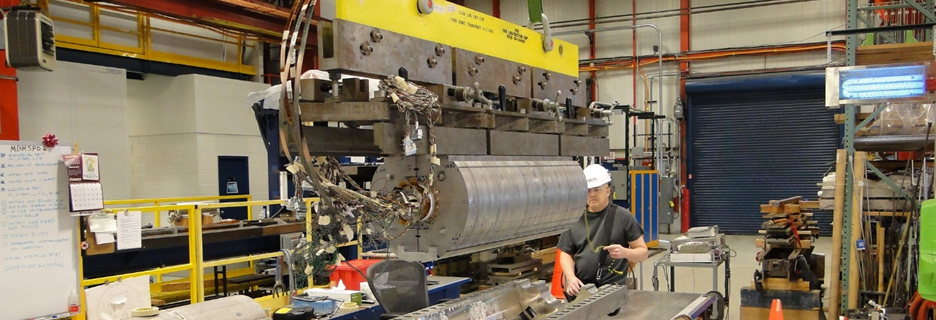
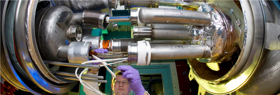
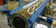
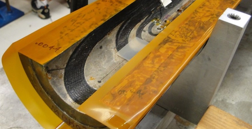
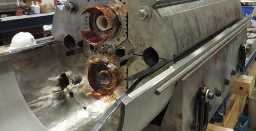
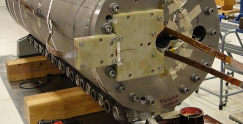 MBHSP02 Magnet assembly (HFM).